Testing GSM Designs: Part 1

GSM overview
Typical system architecture
GSM cell structure
Traffic channel
In the modern wireless world, engineers are faced with many testing decisions. The reality is that air interface standards lie at the heart of many of these decisions. Testing can vary greatly from CDMA to TDMA to GSM to AMPS. Therefore, to properly understand how to test a system, engineers must first understand the key specifications and functionality provided by an air interface standard.
This month, I'm going to start a multi-part series on GSM testing. But, before delving into specific GSM testing issues, I feel it is important to start the first part of this series by providing a brief overview of a typical GSM network. Then, starting next month, I will continue this multi-part series with more in-depth test issues.
GSM overview
The term Global System for Mobile Communication (GSM) has taken on different meaning since its inception in the European wireless market. In the beginning, GSM was strictly seen as the air interface standard for 900 MHz digital cellular operation in the European market. Over time, however, GSM has taken on new forms in the wireless market. Now, GSM is also used as the air interface for European personal communication networks (PCNs) operating in the 1800 MHz band as well as US personal communication services (PCS) systems operating in the 1900 MHz band.
Although there is a great deal of talk about US PCS systems, let's focus in a little closer on the two European GSM networks—GSM-900 and DCS-1800 (also called GSM-1800). The term GSM can be used collectively to describe the GSM-900 and DCS-1800 standards. Despite this, there are some difference between the three networks.
Creating DCS-1800 involved widening the bands assigned to GSM-900 and moving them up to 1.8 GHz. The DCS-1800 standard was created to allow PCN to form, increasing competition in the cellular communications industry. To avoid confusion, the channel numbers (ARFCN) used for DCS run from 512 to 885. On the contrary, GSM-900 channels run from 1 to 124.
With wider frequency allocation, DCS-1800 is able to cope with higher user densities. DCS-1800 mobiles are also designed for lower output powers (up to 1 W). Therefore, cell sizes must be smaller and even higher densities can be achieved.
Typical system architecture
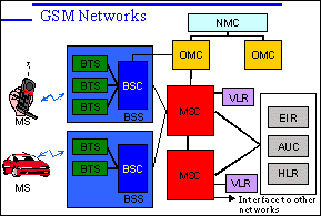
Figure 1 depicts a typical architecture for a GSM system. In this architecture, mobile stations talk to the base station system (BSS) over the RF air interface. The BSS consists of a base transceiver station (BTS), and a base station controller (BSC). It's typical for several BTS to be located at the same site, producing 2 to 4 sectored cells around a common antenna tower.

BSCs are often connected to BTS via microwave links. The BSC to BTS link is called the Abis interface. Typically 20 to 30 BTS will be controlled by one BSC.
A number of BSSs also report back to the mobile switching center (MSC), which controls the traffic among a number of different cells. Each MSC is equipped with a visitors location register (VLR) in which mobiles that are out of their home cell will be listed so that the network will know where to find them. The MSC will also be connected to the home location register (HLR), the authentication center (AUC), and the equipment identity register (EIR), so that a system can verify that users and equipment are legal subscribers. This helps avoid the use of stolen or fraud mobiles.
Additionally, a typical GSM MSC includes links to the operations and maintenance (OMC) organization, network management (NMC) organization, private land mobile networks, the public-switched telephone network (PSTN), and integrated services digital network (ISDN) systems.
GSM cell structure
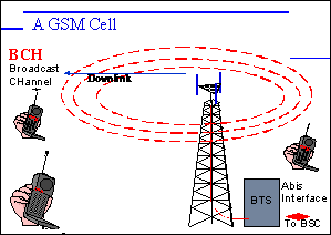
Figure 2 provides a typical view of the cell structure of a typical GSM system. A typical cell in a GSM-900 system can offer up to a 35 km radius while a typical cell in a DCS-1800 systems may feature up to a 2 km radius.

The most obvious part of the GSM cell is the base station and its antenna tower. It's common for several cells to be sectored around a common antenna tower. The tower will have several directional antennas, each covering a particular area. This co-location of several BTS is sometimes called a cell site, or just a base station.
The BTSs are connected to their BSC by the Abis interface. As stated above, the connection between the BTS and BSC can be accomplished several ways. In particular, engineers can use cables, optical fiber, or microwave links (typically used in DCS-1800 applications) to connect these two systems.
In the GSM system, each BTS is fitted with a number of transmit/receive pairs or transceiver modules. The number will determine how many frequency channels can be used in the cell, and depends on the expected number of users.
All BTSs also produce a broadcast channel (BCH). The BCH is like a lighthouse or beacon. It's on all the time and allows mobile to find the GSM network. The BCH signal strength is also used by the network for a variety of user functions. It's a useful way of telling which is the closest BTS to the mobile. Additionally, the BCH has information coded onto it, such as the identity of the network (e.g. Mannesmann, Detecon, or Optus), paging messages for any mobiles needing to accept a phone call, and a variety of other information.
The frequency channel used by the BCH is different in each cell. Channels can be re-used by distant cells, where the risk of interference is low.
Traffic channel
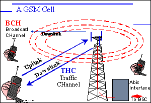
The final important piece in a GSM network is the traffic channel. During a call, mobile phones transmit signals to and receive signals from a base station over a traffic channel (Figure 3).

The TCH is a two-way channel used to exchange speech information between the mobile and base station. Information is divided into the uplink and downlink, depending on its direction of flow.
GSM separates out the uplink and downlink into separate frequency bands. Within each band, the channel numbering scheme is the same. Effectively, a GSM channel consists of an uplink and a downlink.
It's interesting to note that while the TCH uses a frequency channel in both the uplink and downlink, the BCH occupies a channel in the downlink band only. The corresponding channel in the uplink is effectively left clear. This can be used by the mobile for unscheduled or random access channels (RACH).
When the mobile wants to grab the attention of the base station (perhaps to make a call), it can ask for attention by using this clear frequency channel to send a RACH. Since more than one mobile may want to grab attention at the same time, colliding RACHs are possible, and mobiles may need to make repeated attempt to get heard.
Wrap up
That concludes the first part in our multi-part series on GSM testing. In part two of this series, I will provide a more in-depth look at specific testing issues that engineers will encounter in during design. See you next month.
About the author:
Karen Otto is a Customer Education Engineer at Hewlett-Packard's (HP's) Spokane Division. In her position at HP, Karen is responsible for designing training material for cellular and PCS test systems. Before coming to HP, Karen was a design engineer in the television industry, where she worked on picture-in-picture, IDTV, and MPEG satellite decoder projects. She has a BSEE from Purdue University and can be reached at karen_otto@hp.com.
