
Employing the FLEX Protocol in Messaging Applications

By: David Ruimy Gonzales, senior member of Technical Staff, N/A M•CORE Technology Center
Contents
Selective signaling
FLEX family
Signal structure overview
FLEX stack software
ReFLEX
A host of applications
Pagers have become quite popular in the last 10 years and have led to the introduction of a variety of new portable applications that communicate digital messages to central base stations that dispatch the information to one or more locations. Through the development of the next generation paging protocols, such as the FLEX family, new products are emerging such as automatic utility meter readers, smart vending machines that report inventory or service requests, and automobile security systems that can disable the engine and/or report the location of an automobile.
The entire paging process is based on the production of some form of selective signaling (coding) format that will initiate an alert in one specific receiving device (or possibly a group of these devices). It also provides a format in which to deliver some form of message to that device, the pager. The key element in this process is a format that performs the transfer of information in an efficient and effective manner.
Selective signaling
Historically, several formats have evolved to provide selective signaling, such as an early analog two-tone and 5/6 tone sequential formats. While effective, these formats had limitations on system capacity, throughput, and functionality.
To satisfy the demands of the increasing popularity of paging service, the industry turned to true digital formats. Several formats evolved from this need, such as the Golay Sequential Code (GSC) and the Post Office Code Standardization Advisory Group (POCSAG) protocols. In addition to these protocols, the paging industry also saw the development of the FLEX family of protocols, which have been well excepted in the paging and advanced messaging markets.
FLEX family
The FLEX Protocol supports increased transmission speed and capacity. Service providers have adopted the FLEX Protocol because it quadruples the capacity of other paging protocols and significantly improves messaging reliability. Thus, FLEX is a family of wireless transport protocols that greatly enhance the channel efficiency and the cost of traditional paging systems while enabling new value-added wireless services.
There are three messaging systems currently housed under the FLEX family. These include the FLEX protocol for one-way data messaging, the ReFLEX protocol for two-way data messaging, and InFLEXion protocol for mixed-mode analog voice and data two-way messaging systems. Although all three of these protocols are interesting to talk about, let's focus in more on the FLEX and ReFLEX protocols, which are being employed in a majority of new paging/advanced messaging network designs.
All three FLEX protocols build upon the existing systems using POCSAG 1200 and runs side by side with POCSAG on one RF channel. Current 1200 b/s POCSAG systems offer a channel capacity of approximately 120,000 numeric pagers per channel. FLEX provides paging speeds up to 6400 b/s to allow more than 600,000 numeric pagers per channel.
The FLEX protocol maintains data integrity by providing error protection against multi-path fading errors (caused by multi-casting), and by keeping the data-reception electronics continuously in synchronization with the transmission. FLEX also provides roaming capabilities and significantly improves product battery life.
Signal structure overview
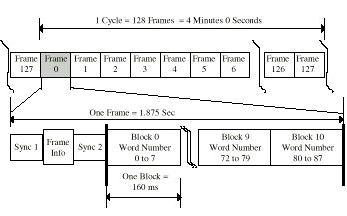
The FLEX paging protocol is a synchronous time-slot protocol that is referenced to an accurate real-time base, GPS system. Each pager is assigned to a base frame in a set of 128 frames (0-127) transmitted during a 4 minute time interval called a cycle (32 frames per minute, 1.875 seconds per frame).
Fifteen FLEX cycles (numbered 0-14, cycle 0/frame 0) occur each hour and are synchronized to the start of the GPS hour. The pager capcode defines its base frame assignment. How often the pager awakes to receive frame information is determined by the collapse value assigned to it that affects battery life.
Each FLEX frame consists of a synchronization and data portion (Figure 1). The synchronization portion consists of a synchronization signal and an 11-b frame information word that allows the pager to identify the frame and cycle in which it resides. A second synchronization signal indicates the rate at which the data portion is transmitted (i.e., 1600, 3200, or 6400 bits per second). Data is transmitted using either 2-level frequency shift keyed (FSK) modulation or 4-level FSK modulation. The 6400 b/s rate is transmitted as four concurrent phases of information using 4-level FSK modulation.
FLEX stack software
The FLEX protocol includes encoding and decoding rules that identify the minimum requirements a paging device, terminal, or other encoding equipment must meet in order to properly format a FLEX data stream for RF transmission and to successfully decode it.
FLEX stack software simplifies the encoding and decoding process, allowing engineers to implement the FLEX protocol into a wide variety of devices and appliances to process information received and demodulated from a FLEX decoder. This software is an application-programming interface (API) that runs on a host processor to manage communication with the FLEX decoder. The FLEX stack software handles the initialization, buffering of received code words, and decoding of separate address, vector and data packets. It also performs phase de-multiplexing, roaming, security, and event notification.
The software consists of three modules as well as public and intermodule application program interfaces that control the FLEX decoder and manage the raw FLEX data (Figure 2).
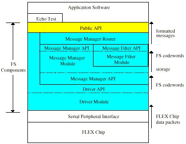
The driver module manages the flow of data from the FLEX decoder and builds raw message data from received data streams. The message manager module stores and manages message data and routes calls to the appropriate API. The Message filter module formats raw message data according to the required format. This format could be ASCI characters, binary data, ideographic character symbols, or any other supported form.
A public application-programming interface (PAPI) complements the three fundamental FLEX stack modules. The PAPI provides a high-level interface that is used by the host software to manage message data, message notification, and the FLEX decoder using eleven function calls.
ReFLEX
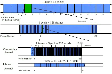
The underlying technology of FLEX allowed for the development of ReFLEX. The ReFLEX protocol provides an asymmetrical two-way data message delivery system for paging applications. It has a synchronous frame structure similar to and compatible with FLEX on a frame basis. It delivers control and data messages to subscriber units on a forward channel (outbound from the base transmitter) and for receiving acknowledgements and messages from subscriber units on a reverse channel (inbound from the subscriber unit to the base receiver).
The acknowledgement functionality described above allows the paging device to "acknowledge" that a message has been received and also permits the service provider to monitor the paging devices' location within a local geographic area using subscriber unit registration. Subscribers with keyboards are able to send back short response messages. Since the return channel is not coupled to the outbound paging channel, the message sent is independent of the "acknowledgement" that the paging device sends back as part of the protocol.
ReFLEX systems are designed to operate on a frequency spectrum with a width that is a multiple of 25 kHz. A 25 kHz band supports a single digital FM control and data message channel, centered on the band. Digital FM channels must remain at a distance of 12.5 kHz from the edges of the available spectrum. A 50 kHz forward channel can support up to three digital FM control and data message channels separated by 12.5 kHz and operated in time lock. Outbound channels operate at 930 to 931 and 940 to 941 MHz range and inbound channels operate at 901 to 902 MHz. The protocol supports systems consisting of up to eight forward control channels (Figure 3).
A host of applications
The FLEX and ReFLEX protocols open an immense number of opportunities for low-cost messaging applications. Stand-alone FLEX hardware decoders are available from a number of semiconductor vendors that interface quite easily to a synchronous serial interface. For example, microcontrollers with on-chip hardware decoders are now available such as the MMC2080 which implements an M•CORE processor with a one-way FLEX decoder, on-chip RAM and ROM and a number of peripherals.
References:
1. The FLEX Family of Messaging Protocols, AMTTG145, March 1998, Motorola Advanced Messaging Technical Training Manual.
2. FLEX Technologies for Today and Tomorrow, Steve Torp
3. Motorola's ReFLEX Technology, Chipset Solutions and Potential Applications, Omid Tahernia, Eric Eaton, Tom LaRotonda, Gavin Bourne, Embedded Systems Conference, Chicago, March, 1999.
Author's Note
I would like to say special thanks to John Wilson, microcontroller applications and TDMA/messaging platform manager in Motorola's Wireless Subscriber Systems Group, for his contributions to this article.
About the author:
David Ruimy Gonzales is a senior member of the Technical Staff at the M•CORE Technology Center, Motorola Semiconductor Products Sector (SPS), P.O. Box 6000, Austin, TX 78762. Phone: 512-342-6167; Fax: 512-342-6041.
Edited by Robert Keenan