
Electrostatic Discharge (ESD) Testing Simulation
Electrostatic discharge testing is crucial for electronics manufacturers worldwide to assess ESD susceptibility, impacting annual costs, warranty claims, and consumer confidence, making the ability to simulate ESD in XFdtd valuable for optimizing ESD mitigation during product development.
ESD Waveforms
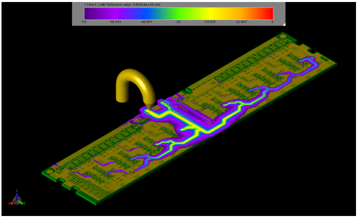
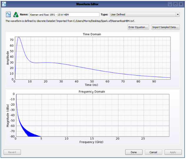
ESD testing procedures and waveform models are defined by numerous standards from organizations including the American National Standards Institute (ANSI), JEDEC, and International Electrotechnical Commission (IEC), among others. The human body model (HBM), which approximates a discharge from a charged human fingertip to a grounded device, and the charged device model (CDM), which approximates a discharge from a charged device to another conducting object at a lower electrostatic potential, are the most common and widely used ESD models. These tests are generally performed using ESD Simulators, or ESD Guns, to apply high speed, high voltage pulses to various points of the device under test (DUT). Using XFdtd’s user defined waveform feature, engineers can import ESD waveforms defined by the various testing standards and use them to create ESD current sources in their XFdtd project. At this point, ESD simulator/gun models can be created and used to excite the DUT geometry at locations of interest and the resulting electromagnetic fields and current flows can be simulated and analyzed.
Dielectric Breakdown Prediction
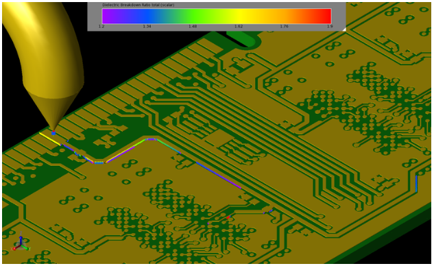
Even for an experienced engineer it can be extremely challenging to pinpoint the location of an ESD failure during testing, and in some cases, to determine if a failure occurred at all. To solve this, the dielectric strength of materials can be defined in XFdtd. The dielectric strength of a material defines the maximum electric field it can withstand without experiencing dielectric breakdown (i.e., losing its insulating properties). Upon adding the dielectric strength of materials to an XFdtd project, it is possible to monitor FDTD cell edges for potential dielectric breakdown during transient simulations using a dielectric breakdown near field sensor. At the conclusion of an XFdtd simulation, cell edges which exceeded their dielectric strength can be easily located.
Circuit Component Overvoltages and Overcurrents
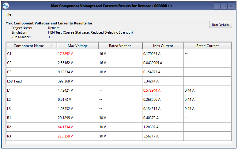
Generally speaking, circuit component failure is encountered more frequently than dielectric breakdown failure during ESD testing. To predict circuit component failures, rated voltage and current input parameters, which can be obtained from electronic component data sheets, can be added to XFdtd’s circuit component definitions. Upon completion of an XFdtd simulation, components that exceeded their rated design parameters are reported by XFdtd’s Max Component Voltages and Currents result dialog.
Optimize ESD Mitigation
While simulation cannot and should not entirely replace hardware testing, it can provide ESD engineers with insight into probable locations of ESD failure and will allow ESD mitigation designs to be optimized prior to the hardware prototyping stage. XFdtd’s ability to pinpoint locations at risk of experiencing dielectric breakdown and report circuit components exceeding their design parameters during an ESD event should reduce product development costs and time to market, while improving product reliability and consumer confidence.
Click Here To Download: