
Blocking RF Switch Matrix
A blocking RF switch matrix can achieve high levels of isolation and lower levels of insertion loss because of their internal switches (which exhibit high isolation and low loss characteristics). They’re the simplest type of available RF switch matrix configurations.
In a blocking switch matrix configuration, any of the inputs can be switched to any unused output. An output is used and not available to other inputs if an input has already been switched to that port. For example, a 10 x 10 blocking matrix can simultaneously switch input 1 to output 7, input 2 to output 5, input 3 to any output except 7 or 5 (because they are already occupied by input 1 and input 2 respectively), etc.
Continuing the 10 x 10 example, this matrix requires a 1 x10 switch at each input and at each output for a total of twenty 1 x 10 switches. Each input then has ten internal connection points and each output has ten internal connection points. These connection points are attached to each other via 100 internal cables, or through other interconnect methods.
The blocking matrix architecture is accomplished with a set of input switches, a set of output switches, and interconnects between the input and output switches.
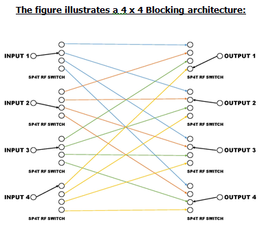
In the 4 x4 blocking illustration, Input 1 and Input 3 are not connected to any output. Input 2 is connected to Output 3 and Input 4 is switched to Output 1. No other input can be switched to Output 3 or Output 1 as long as Input 2 and Input 4 are connected. The other inputs are “blocked” from Outputs 3 and 1. The other two unused outputs are still available for connection to an input.
Corry Micronics offers non-blocking and super non-blocking configurations as well. To learn more about their switch matrix offerings, download the datasheet.